| Beginning |
Surely, some of you played with the thought of integrating LEDS and exhausts in a control. I build myself a simple control for fans and LEDs. Here is it: the guidance:
| Tools |
I wanted to control two exhaust cycles with the control and switch altogether three LED groups. To integrate perfectly all devices into a housing I have used an old CD ROM housing.
A meaningful housing, suitable size; alltogether a good-looking selection. Since i work in a computer company (software+hardware) constantly any broken hardware
is available for me.
Then naturally the base circuit board and the components for the control circuit board. A handful of 1x AROUND switches and a little bit of soldering wire. finished. And
here the whole complete purchase list:
FanBus:
CD ROM housing
1x hole circuit board
2x Potis 4,7 kOhm
2x Resistor 240 Ohm
2x Ceramic capacitor 0,1 uF
2x Ceramic capacitor 1 uF
2x LM317 (T)
2x 5 1/4 Plugs
LED Controll:
1x Switch (use on with 2 or more contacs)
Wire with fitting plugs
| Die Schaltung |
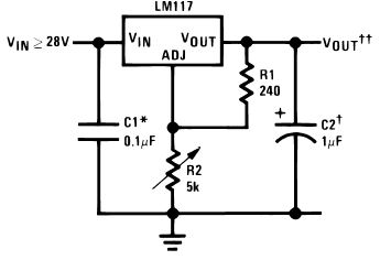
The exhaust circuit is quite simply and fast structured. By the integrated circuit LM317 (T) the entire circuit becomes quite simply and relatively safe by a small expenditure of external components in the reproduction.
| As is to be inferred from the connection diagram, are only few components
needed. |
|
|
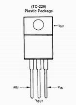
The Pinout of the Voltage regulator IC. |
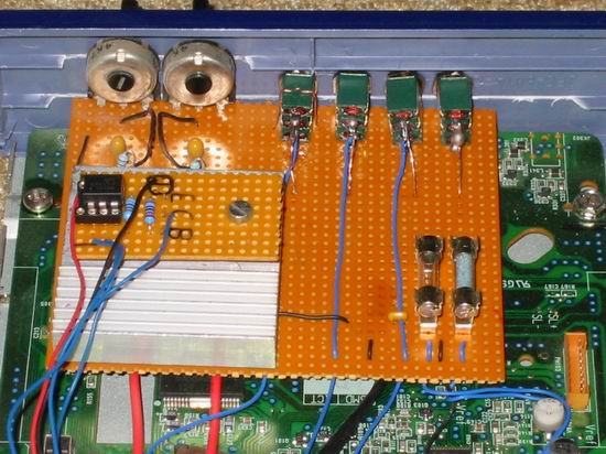
First we should plan the circuit board. At the simplest and safest it is, to draw with a pin (CD pin or the like) the conductive strip way (don´t know if this is the right word) oversize awls. Then attach and solder the components together. I use directly the wires at the components around the conductive strips to interconnect - those are always too long so why do not thus solder and pinch off afterwards? I have to build the rocker switches into the Front fastened 100% so the switches are even one. Not which I solder afterwards and one states that the switches do not fit into the drillings intended - and I am no a type measure myself with a pocket calculator and geo triangle....
Then I soldered the rocker switches on the circuit board. So that the IC's does not come into sweating, I stuck still another small
cooler from an old socket7 cpu (such things lying around @home) directly with thermally conductive adhesive on the IC. I connect three rocker switches centrically with the LED output and in each case a page with +5V and the other one with +12V.
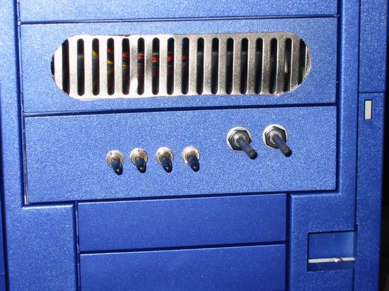
So I can sitch the LED's between bright and darkness. I can still switch off the 12V line over the fourth rocker switch. Up to the installation on the CD ROM circuit board the controll can rest only times. Now the CD ROM must be
modded.
| The housing |
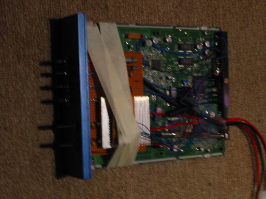
Break the housing and remove all things in it. Then remove (abort) all components which are away forward and fix the circuit board at the housing bottom by means of hot adhesives. We should fit the Front in best now. With my CS 901 housing I have cut off the lateral connecting pieces to fit the Front into the housing. Practical way such a CD ROM has in the back equal a current supply and a broad (ATA or SCSI) link that ideally alienate for these purposes leaves itself.
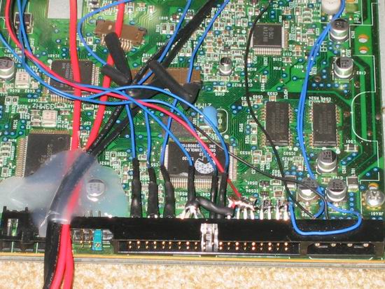  |
I soldered the current supply for the circuit board directly with the link on the inside (yellow + 12V/red + 5V!!) and the ATA link with the Dremel processes. For this I separated the upper series pins simply at the circuit board. I soldered the lower series with a wire and connected it with the mass (-). I summarized the Pins which is situated above in each case in tripartite groups and with one approx.. 10 cm long wire solders. Beautifully still with heat shrink sleeve provided with it so everything has its order. A Few hot adhesive for the adjustment of the connecting wires cannot harm also. In the upper picture you can see still good the access lines for the exhausts (right). I fastened these for the sake of simplicity with tidy hot adhesive. |
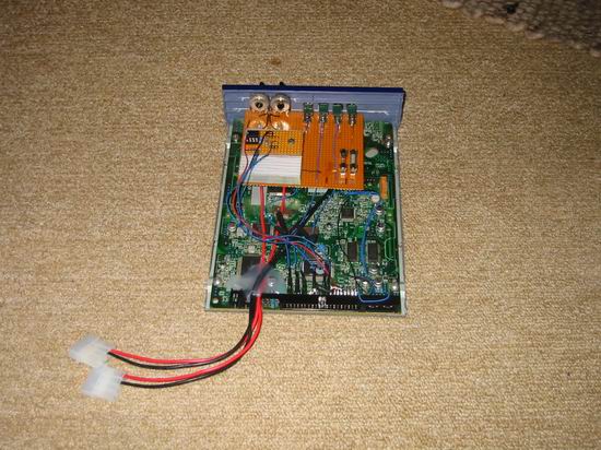
| The assembly |
If we arranged once the control and the CD ROM housing so far, the assembly can begin. I stuck the control circuit board and the Front on the CD ROM circuit board with hot adhesive and soldered the control wires at the circuit board. As already described I decided above for the exhaust supply of the solution by voltagekable. The suitable plugs are available also in the electronics specialist shop. A cable solution has to ensure the advantage little more flexibility in the PC housing . Everything stuck together firmly and soldered the test run can begin. A current supply should be fast found and a few LEDS anyway. The exhausts should be all provided with 5 1/4 inch power connections, if necessary you must buy some sockets in addition and solder to the exhaust cables. If the test run is positive, there would be nothing more in the way to install the controll into the housing.
| Impressions |
 |
 |
 |
 |
 |
 |
greetz, hartwareguru